- 您现在的位置:买卖IC网 > Sheet目录321 > DM300024 (Microchip Technology)KIT DEMO DSPICDEM 1.1
�� �
�
�dsPICDEM? 1.1 Plus Development Board User’s Guide�
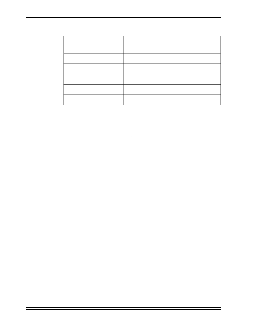
��TABLE� 5-2:� OSCILLATOR� SELECTION� PARAMETERS� (1)�
�Oscillator� Selection� on�
�dsPICDEM?� 1.1� Plus�
�Demo� Board�
�Crystal� (X3)�
�Mini� Crystal� (X2)�
�Canned� Oscillator� (U5)�
�RC�
�External� Clock�
�Modifications� on� dsPICDEM?� 1.1� Plus� Demo� Board�
�R33,� R34,� R20,� C20,� C21� and� X2� open,� U5� empty.�
�Crystal� in� X3,� caps� in� C33� and� C37.�
�R20,� R33,� R34,� C33,� C37� and� X1� open,� U5� empty.�
�Crystal� in� X2,� caps� in� C20� and� C21.�
�R20,� R33,� R34,� C20,� C21,� C33,� C37,� X2� and� X3� open,�
�U5� installed.�
�R33,� R34,� C20,� C21,� C33,� X2� and� X3� open,� U5� empty.�
�Cap� in� C37� and� resistor� in� R20.�
�R20,� C20,� C21,� C33,� C37,� U5,� X2� and� X3� open.� 0� ohm�
�installed� for� R33� and� R34.�
�Note�
�5.1.16�
�1:�
�The� oscillator� circuit� schematics� are� shown� in� Figure�
���Reset� Switch�
�By� placing� J10� jumper� in� the� MCLR1� position,� the� Reset� switch� connected� to� the�
�processor� MCLR� pin� provides� a� hard� Reset� to� the� dsPIC� DSC� device.� By� placing� J10�
�jumper� in� the� MCLR2� position,� the� Reset� switch� is� connected� to� the� PIC18F242� LCD�
�controller.�
���5.1.17�
�Prototyping� Area�
�A� prototyping� area� and� associated� header� are� provided� on� the� development� board� to�
�enable� additional� ICs� and� attachment� boards� to� be� added� (see� Figure�
��5.1.18�
�Sample� Devices�
�A� sample� dsPIC� DSC� device� programmed� with� the� demonstration� code� is� included� in�
�the� dsPICDEM?� 1.1� Plus� Development� Board� Kit.� The� 80-pin� TQFP� is� soldered� to� a�
�1.5”� x� 1.5”� adaptor� PCB,� which� is� inserted� onto� the� emulation� header,� J11� and� J13-J15.�
�Handle� the� device� carefully� when� inserting� and� extracting� the� adaptor� board.� The�
�orientation� of� the� adaptor� board� is� important.� The� Microchip� logo� and� device� part�
�numbering� should� be� aligned� to� read� from� left� to� right� before� insertion� of� the� adaptor�
�board.� The� pin� 1� index� marker� of� dsPIC30F� device� should� align� with� the� lower� left�
�45°� corner� of� the� 80-pin� QFP� footprint� (pin� 1� of� Emulation� Header� J14).�
���DS70099D-page� 66�
�?� 2006� Microchip� Technology� Inc.�
�发布紧急采购,3分钟左右您将得到回复。
相关PDF资料
DM330012
KIT USB STARTER FOR DSPIC33E
DM330013
MICROSTICK DSPIC33F/PIC24H BOARD
DNET1
SURGE SUPPRESSOR ETHERNET RJ45
DR-8094
RACK DOUBLE 84"X20.25"X36" BLK
DR-IAC5E
INPUT MODULE AC 5VDC
DRIDC24A
INPUT MODULE DC 34MA 24VDC
DRODC24
OUTPUT MODULE DC 13MA 24VDC
DRR-40A
MODULE REDUNDANCY 40A DIN RAIL
相关代理商/技术参数
DM300027
功能描述:开发板和工具包 - PIC / DSPIC 16-bit Starter Demo Board RoHS:否 制造商:Microchip Technology 产品:Starter Kits 工具用于评估:chipKIT 核心:Uno32 接口类型: 工作电源电压:
DM-3-000-K
制造商:PacTec 功能描述:Case, Plastic; ABS; Black; 11.46 in.; 3.38 in.; 10.4 in.; UL 94-HB Rated 制造商:PacTec 功能描述:ENCLOSURE, DESKTOP, PLASTIC, BLACK; Enclosure Type:Desktop; Enclosure Material:Plastic; Body Color:Black; External Height - Imperial:3.38"; External Height - Metric:86mm; External Width - Imperial:10.4"; External Width - Metric:264mm;RoHS Compliant: Yes
DM-300-C
制造商:Greenlee Textron Inc 功能描述:DMM 1000V RMS
DM-301
制造商:Labfacility Limited 功能描述:SENSOR PT100 THIN FILM 2X2.3MM CL B 制造商:LABFACILITY 功能描述:SENSOR, PT100, THIN FILM, 2X2.3MM, CL B 制造商:LABFACILITY 功能描述:TEMPERATURE RTD SENSOR, -70C to +500C, 100 OHM; Sensing Temperature Min:-70C; Sensing Temperature Max:+500C; Resistance:100ohm; Sensor Terminals:Through Hole; Temperature Sensing Range:-70C to +500C ;RoHS Compliant: Yes
DM30103J
制造商:ELMCO 功能描述:
DM30113G
制造商:n/a 功能描述:DM30X311 S7C8B
DM30-113G
制造商:n/a 功能描述:DM30X311 S7C8B
DM30133J
制造商:n/a 功能描述:DM30X313 S7C8B